Lab 3: Texturing Objects & Per-Pixel Lighting Computations
Lab 3 Objectives
To bring more realism into our scenes we are going to learn about two important concepts in computer graphics: texure mapping, and lighting. We won't go into full details about how they work (you'll learn that in lecture) but instead learn how to set them in OpenGL. In this week's lab you'll learn about the following:- Texture Mapping
- Per-Pixel Lighting Setup (You'll do the actual computation in project 2)
Texture Mapping
At a high-level, texture mapping means applying any type of image to one or more faces of a 3D object. Texturing an object involves three steps:- Loading the image (i.e., the texture) into an texture object, which allows OpenGL to supply to the shader program.
- Load a set of coordinates known as texture coordinates for each vertex. Since a triangle can be transformed (i.e., translated, rotated, scaled), we use texture coordinates to follow the movement of the vertices to make the texture seem real on the face of an object. During rasterization, the GPU will interpolate the texture coordinates across the traingle provide them to the fragement shader.
- Inside the fragment shader, we map these interpolated texture coordindates to the texture. This action is known as sampling , which results in a texel (i.e., a pixel in a texture) being produced. The texel often contains a color which is used as the "out" color for a fragment.
OpenGL supports several types of textures such as 1D, 2D, and 3D that can be used for different techniques. In this course, we will mostly be working with 2D textures.
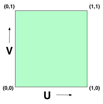
Texture coordinates are specified in texture space , which is simply the normalized range [0,1]. By convention, we use U and V as the axes of the texture space where U corresponds to the x-axis and V corresponds to the y-axis. OpenGL treats the values of the UV axes as going from left to right on the U axis and down to up on the V axis. Take a look at the following image:
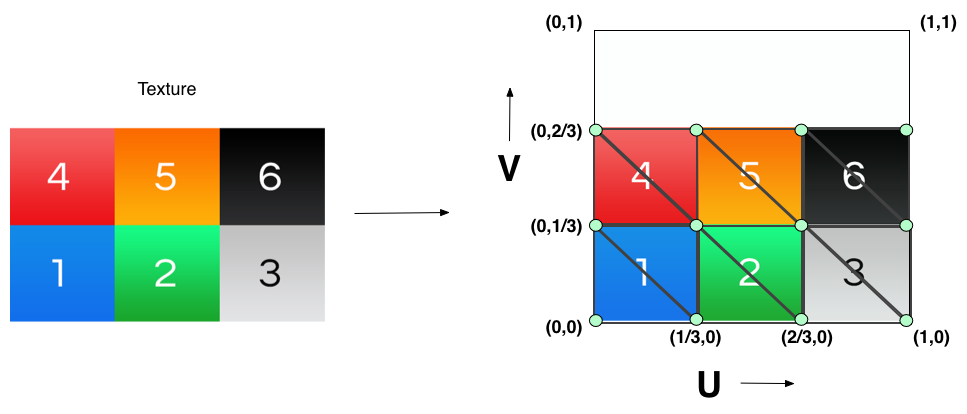
Thus, for this lab we are going to specifiy the texture coordinates for the cube as such:
Part 1: Textures in OpenGL
The sections below discuss creating textures and using them during the rendering process.Generate/Setup a texture
The CS237 library provides a few wrapper functions around the OpenGL texture functions that allow you to easily load an image and create/setup a texture based on that image:
//1
cs237::image2d * image = new cs237::image2d("PATH_TO_PNG_FILE");

//2
cs237::texture2D * texture = new cs237::texture2D(GL_TEXTURE_2D, image);

//3
texture->Bind();

//4
texture->Parameter(GL_TEXTURE_MIN_FILTER,GL_LINEAR);
texture->Parameter(GL_TEXTURE_MAG_FILTER,GL_LINEAR);
- The cs237::image2d type is part of the cs237 texture library. Creating a cs237::image2d object loads a 2D image from a png file into memory, which then can be loaded into an OpenGL
texture object. You only need to specify the file path when creating the object and it handles the rest.
- Next, we create the OpenGL texture given the image data we previously loaded.
The constructor takes in two arguments: target, and the image data, which will be loaded into the texture. The target is OpenGL specific and is needed to tell OpenGL what type of texture 2D will it target. Mostly in this course it will always be GL_TEXTURE_2D but there are other 2D targets you can use (e.g., GL_PROXY_TEXTURE_2D, GL_TEXTURE_RECTANGLE, etc.).
- We are about to setup additional parameters for this texture so we need to tell OpenGL that "Hey, the upcomming texture calls are related to this particular texture object", similiar to binding a VBO and then pusing data into the buffer. The texture already knows its target (i.e. GL_TEXTURE_2D) so it binds it to that target using the Bind() function. Texture objects can be bound to targets simultaneously. For example, I could bind a 3D texture to the GL_TEXTURE_3D target and bind a 2D texture to the GL_TEXTURE_2D target and work on them both at the same time.
- The Parameter function of a texture initializes many aspects related to the texture sampling operation. Rarely is a texture and the triangle it's covering proportional to each other. Many times the triangle is either a bit smaller or larger than the texture. We use these parameters to match to the proportion of the triangle. We specify the magnification parameter (GL_TEXTURE_MAG_FILTER) to handle when the triangle is larger than the texture (i.e., it is very close to the camera), which means there are several pixels covered by the same texel. The minification (GL_TEXTURE_MIN_FILTER) parameter to handle when a triangle is smaller than the texture (i.e., it is very far from the camera), which means several texels are covered by the same pixel. Here we select the linear interpolation filter type (GL_LINEAR) for both parameters, which provides good looking results.
Rendering a Texture
The below code needs to happen if you will use a texture to render an object://1: Activate the first texture unit. CS237_CHECK(glActiveTexture(GL_TEXTURE0)); //2 : Activate the first texture unit. CS237_CHECK(glActiveTexture(GL_TEXTURE0)); //3: Bind the texture to its target texture->Bind(); //4: Assign the uniform sampler to the first texture unit. cs237::SetUniform(_samplerLoc, 0);
- In order to use a texture inside the shader program, we need to bind it to a texture unit. The texture will then live inside the texture unit and the shader uses the texture unit to get access to the texture object. A benefit of having a texture unit is that it can handle several texture objects simultaneously, as long as the textures are of different types (i.e. 1D, 2D, 3D texture). Thus, before every draw call we need to: activate a texture unit and then bind the texture object to the activiated texture unit so that it can be sampled within the fragment shader.
The function glActiveTexture activates a texture unit. The function takes in an enumeration (i.e. GL_TEXTURE0, GL_TEXTURE1, GL_TEXTURE2, and so on...) that correspoonds to which texture unit to activate. You can more than one texture unit activated simultaneously and the number available is dependent on the capability of your graphis card.
- Next, if the texture unit activated (i.e. texture unit 0) then we bind our texture to this texture unit by calling the bind function again.
- Lastly, we need to assign the uniform sampler variable defined in the fragment shader to the texture unit that it will use for sampling.
The function cs237::SetUniform sets the index of the texture unit to use for sampling. _samplerLoc is the uniform location of the sampler defined in the fragment shader and "0" corresponds to telling the sampler it should be sampling from texture unit 0. For example, if you had the following sampler variable defined in your fragment shader:
uniform sampler2D sampler;
then you will use the UniformLocation function to get its location:_samplerLoc(sh->UniformLocation ("sampler")),
where "shader" is the shader program and then you can assign the texture unit it points to by using glUniform1i.Note: the actual index of the texture unit is used here, and NOT the OpenGL enum GL_TEXTURE0 (which has a different value).
Part 2: Shaders & Per-Pixel Light Computations Setup
In order to perform per-pixel lighting on an object, you will need to supply normals for each vertex defined within your mesh. In OpenGL, you will pass these normals into the vertex shader (along with your vertex positions, and texture coordinates) by using vertex attributes. This means you will need to create a VBO for your normals and set their attribute information just like vertex positions. You will then pass the normal from the vertex shader as an "out" variable to the rasterizer.
There will also be additional information you'll need to pass to the fragment shader in relation to lighting (e.g. ambient, direction, intensity, etc.). This can be done by defining these properties as uniform variables and using them in the fragment shader where lighting will be computed.
Your shader source files should look something like this:
- Vertex Shader:
#version 410

uniform mat4 modelView;
uniform mat4 projection;

layout (location = 0) in vec3 position;
layout (location = 1) in vec3 normal;
layout (location = 2) in vec2 tCoord;

out vec2 f_tCoord;
out vec3 f_normal;

void main ()
{
   /* ... */
}
Inside the main function, you will need to convert your position into clip coordinates (just like last lab), pass and transform the normals, and pass the texture coordinates out of the vertex shader into the fragment shader (i.e., f_tCoord and f_normal). - Fragement Shader:
#version 410

uniform sampler2D sampler;

/** Uniforms you will use for lighting (and maybe more...) **/
uniform vec3 direction;
uniform vec3 ambient;
uniform vec3 intensity

in vec2 f_tCoord;
in vec3 f_normal;

out vec4 fragColor;

void main ()
{
    vec3 norm = normalize(f_normal); //renormalize the normnal

    /* This is the color for the fragment without lighting. You will use the lighting equation
      defined in the project to compute the frag color with lighting included. */
    fragColor = texture(sampler,f_tCoord);
}
You will notice the new uniform variable called "sample" that has the sampler2D type. This is an example of a sampler uniform variable. Remember this variable will be assigned to a texture unit that you assigned.The main function uses the GLSL texture function (and there are a few of these) to sample the texture. The first parameter is the sampler uniform varable and the second is the texture coordinates. The function will return the sampled and filtered texel, which is the color for this particular fragment shader.
Note: For your project this will also go through a few more computations in relation to lighting, which will use the normal, to produce the final color for the fragment.
Part 3: Actual Lab (Texture a Cube)
Inside your lab3/src directory you will see an updated view.hxx and view.cxx that includes a new representation of the cube. A cube is now defined by having six walls that include the information such as vertex positions, color, texture coordinates, and the normal for each vertex. You should convert these walls into a mesh representation by using the Mesh struct definition and the loading functions. Use GL_TRIANGLE_FAN instead of GL_TRIANGLES as the drawing primitive target. Thus, you will probably want to store these meshes in an array (one for each wall). Here's a couple of additional notes about getting texturing working:- You will need to copy over some of the code and files from lab2. Mainly the mesh files and parts of the code from render.cxx, and view.cxx. Again Use GL_TRIANGLE_FAN instead of GL_TRIANGLES as the drawing primitive target when creating your meshes.
- You will probably want to add the following functions to your mesh struct:
//! initialize the texture-coordinate data buffer for the mesh
void LoadTexCoords (int nCoords, cs237::vec2f *tcoords);

//! initialize the normals data buffer for the mesh
void LoadNormals (int nVerts, cs237::vec3f *norms);
You will use these functions to load your normals and texture coordinates into their OWN VBO. This means you will need to create buffer ids for texture coordinates and normals. Loading will look VERY similiar to your LoadVertices function becasue you are loading vertex information. This means you will need to bind the buffer ids of these new buffers to GL_ARRAY_BUFFER and use glBufferData to load their information into their VBO. You will also need to set the attribute information using glVertexAttribPointer and glEnableVertexAttribArray. Use the following vertex attribute locations for the attributes:
/*! The locations of the standard mesh attributes.  The layout directives in the shaders
 * should match these values.
 */
const GLint CoordAttrLoc = 0; //!< location of vertex coordinates attribute
const GLint NormAttrLoc = 1;  //!< location of vertex normal attribute
const GLint TexCoordAttrLoc = 2;  //!< location of texture coordniate attribute
Note on Normals: A wall only supplies one normal vector. The normal vector is the same for each vertex position inside a wall. This means you should pass an array that duplicates the normal vector for each vertex position. - Use the texture setup/render code in the previous sections for texture mapping the cube. Use the image inside the data to texture map the cube. You will supply "../data/cubetex.png" to your cs237::image2d object. There are some hints in the code that tell you where to place this code.
You can use the shader code in the previous section as the vertex and fragment shaders for your shader program.
- Make sure to enable depth-testing inside the renderer's enable function:
CS237_CHECK( glEnable (GL_DEPTH_TEST) );